 Mr Kidman's Classroom





Revise the key ideas
Circuit principles
- Systems and subsystems — A system combines components to achieve a purpose. An electronic product can be described as input, process and output, with a power supply supporting it. A light sensor provides information, a controller makes a decision and a motor produces movement. Describe the signal and energy paths separately so a control input is not mistaken for the power driving the actuator, an output device causing physical action, such as a motor.
Follow information from the sensor to the controller separately from energy supplied to drive the motor. The sensor signal does not itself provide all the energy for that movement.
- Safe power supplies — Use only the school-approved low-voltage supplies and components under the required supervision. Match voltage, current needs and polarity where relevant: connecting positive and negative terminals the correct way for the component. A battery can still overheat or cause damage if short-circuited, so low voltage does not mean every connection is safe. Mains wiring, damaged batteries and improvised power arrangements require qualified adult handling, not a revision exercise.
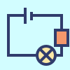
- Complete circuits — Current needs a complete conducting path through a circuit. A switch can open or close that path. Short-circuiting a supply bypasses intended resistance and can produce excessive current. Follow a checked circuit diagram, inspect connections with power off and use the teacher's test procedure rather than repeatedly powering an uncertain arrangement.
- Series and parallel paths — In a simple series circuit, components share one path, so opening it stops current throughout that path. Parallel branches provide separate paths across the supply. Adding components affects current and voltage differently depending on the arrangement and components. Use an appropriate schematic to reason about a real circuit rather than assuming that extra components always make every output brighter.
- Resistance and component ratings — Resistance influences current for a given potential difference; for an appropriate resistor, V = I × R. A 100 Ω resistor with 0.02 A through it has 2 V across it. Real components have ratings and may not follow this relationship in the same way. LEDs need the appropriate orientation and current-limiting arrangement in a checked school circuit.
In V = I × R, V is potential difference in volts, I is current in amperes and R is resistance in ohms. For the stated resistor example, 0.02 × 100 = 2 V. This does not mean every component behaves like that resistor.
Inputs, processing and outputs
- Sensors and transducers — A sensor responds to a physical condition such as light, temperature or movement, providing a usable signal. A transducer converts energy from one form to another; sensors and output devices can be transducers. A light-dependent resistor changes resistance with illumination, so a circuit is needed to turn that change into a signal a controller can use.
- Digital and analogue signals — A digital input is interpreted as a set of distinct states, often on or off; an analogue signal can vary across a range. A controller may convert an analogue measurement into a number before comparing it with a threshold. Resolution and noise affect readings, so a displayed number is not automatically an exact measurement of the physical world.
Compare an on/off switch with a sensor that can measure many different light levels. Resolution is the smallest change the system can distinguish. Noise is unwanted variation in readings, which can make repeated readings differ even when the condition changes little.
- Output devices and drivers — An LED produces light, a buzzer sound and a motor movement. A controller's output pin may not safely supply the current an actuator needs, so a suitable driver circuit and power arrangement can be necessary. Do not connect a motor directly merely because its wires fit. Use the checked components and design supplied through the school's practical instruction.
- Logic and thresholds — A controller can turn an output on when conditions are met, such as light below a threshold AND a switch enabled. Test both conditions and the equality boundary. If a reading fluctuates near one threshold, the output may rapidly switch on and off. Different on/off thresholds can reduce this behaviour, but the values need testing for the real use.
A threshold is the level where a decision changes. For a fictional rule “switch on when light is below 20 AND the switch is enabled”, test readings of 19, 20 and 21 with the switch enabled and disabled. At exactly 20, “below 20” is false. These are practice values, not a setting for every real device.
Programmable control
- Microcontrollers — A microcontroller combines processing, memory and input/output facilities for programmed control. It runs stored instructions that read inputs, make decisions and control outputs. It does not understand the user's goal independently; the program and connected hardware must define appropriate behaviour. A working simulation should be checked against the limitations and ratings of the actual device.
- Control sequence — Specify initial state, input readings, decisions, outputs and repetition. A fictional dark-activated lamp could begin off, read a light value, compare it with a threshold and update the lamp repeatedly. Include what happens when the sensor is disconnected or a reading is unsuitable where relevant. A flowchart should represent both branches and a safe stopping or reset arrangement.
- Open and closed loop — Open-loop control issues actions without checking the resulting output against the target. Closed-loop control uses feedback to compare a measured result with the desired state and adjust behaviour. A timed heater and a temperature-controlled heater illustrate the difference in principle; actual heating devices require appropriate safety systems beyond a classroom control model.

In this simplified safe model, a sensor measures the result and returns feedback for comparison with a target; the controller adjusts the output. Actual appliances need their own safety systems. Full-size diagram In the timed model, a command runs for a set duration without checking the resulting temperature. In the temperature-controlled model, the sensor measures the result, which returns to the controller for comparison with the target. Follow that return path on the existing feedback diagram. Actual heaters need additional appropriate safety systems.
- Testing and debugging control — Check hardware connections, power and code systematically rather than changing them all at once. Predict expected readings and outputs, test one condition at a time and record actual behaviour. Include normal operation, boundary values and relevant fault conditions within safe arrangements. A correct program cannot compensate for an incorrectly rated or disconnected actuator.
Integrated product design
- Power and environmental choices — Consider energy source, expected operating time, maintenance and end-of-life handling. A battery-powered product needs an accessible safe replacement or charging arrangement suited to its users. A lower-power component can help operating time, but the whole system and use pattern matter. Do not claim a device is sustainable solely because one part uses less electricity.
- Evaluating an intelligent product — Test the integrated product against its specification and user needs, including response, reliability, clarity and safe physical design. Explain how sensor information changes the output and what practical limits remain. 'Intelligent' here means programmed responsive behaviour, not human understanding or guaranteed correct decisions in every situation.

