Component relationships — A processor executes instructions using registers and arithmetic/control circuitry; main memory stores currently addressable instructions/data, and I/O controllers coordinate external devices. These components communicate through agreed signalling and data-transfer mechanisms. A storage drive is not the same component as the processor's current instruction register merely because both can hold bit patterns.
Bus concept — A bus is a communication pathway/protocol shared by relevant components, carrying addressed transfers and control under a defined system design. The school model distinguishes address, data and control buses by role. Real systems can use different physical links or multiplexing, sharing a pathway between different signals or transfers according to an agreed scheme, so the conceptual bus categories do not require three visibly separate identical ribbon cables.
Address bus — The address bus identifies a memory or I/O location for a transfer under the architecture's addressing scheme. In a simple processor-controlled memory transaction, the processor supplies the address; an address is not the contents to be transferred. An n-bit address field can identify 2ⁿ distinct locations before any reserved-address or mapping constraints.
Data bus — The data bus transfers instruction/data bit patterns between relevant components. Its width affects how many bits can be transferred in one bus operation under the model, while addresses identify which location. A wider data bus does not automatically enlarge the count of addressable locations; transfer width and address width are different measures.
Control bus — Control signals coordinate operations such as read, write, timing, interrupt requests and acknowledgements under the chosen design. Some originate at the processor and others at devices, so the control category is not universally a one-direction numeric-data channel. A valid address alone does not specify whether a read or write is intended.
Addressable units and capacity — Memory has identifiable locations whose unit size is specified, commonly one byte in a byte-addressable model. A 16-bit address bus identifies 65,536 locations: 64 KiB if each holds one byte, or 128 KiB if each holds two bytes. State location size and reserved mappings before turning an address count into a byte capacity.
I/O controllers — An I/O controller mediates the device's transfer/control interface and exposes relevant status/data operations to the rest of the system. It can buffer transfers or signal readiness/completion as defined. An application normally requests an operation through software layers rather than independently driving every physical device line.
Stored programs, von Neumann and Harvard
Stored-program principle — Machine instructions are stored in addressable memory and fetched for execution rather than the processor's task being determined only by permanently rewired circuitry. Instructions and data are represented by bit patterns under a format. The processor follows execution semantics using arithmetic, logical and control operations; stored program does not mean every file on a drive is already executing.
Von Neumann model — The basic von Neumann model uses a shared memory/addressing and transfer path for instructions and data. It supports flexible use of the same addressable store, but instruction fetch and data transfers can contend for a shared path. General-purpose systems commonly use this as a conceptual foundation; real cache organisations can mix architectural features.
Harvard model — The basic Harvard model separates instruction and data memories/address spaces and transfer pathways. This can permit instruction and data access concurrently and allow different memory widths/properties. Embedded and digital signal-processing designs often use Harvard features, but the label does not automatically guarantee a particular program is faster or every memory is the same size.Basic von Neumann uses a shared instruction/data memory and transfer resource; basic Harvard separates their memories/address spaces and paths. The Harvard instruction arrow shows fetching into the processor, while the data paths show reading and writing. These are conceptual access directions, not a physical bus wiring plan. Real cache/main-memory organisation can combine features.
Comparing real systems — A processor can use separate instruction/data caches while presenting a unified main-memory view, sometimes described as modified Harvard organisation. Distinguish the conceptual course models from every detail of a current chip. Explain which actual paths or address spaces are shared/separate rather than deciding architecture solely from a device's brand or whether it is portable.
Sequential model and parallel implementation — The introductory fetch/decode/execute model describes instructions in their intended program order, with branches changing that order. Modern processors can overlap or reorder internal work while preserving required architectural behaviour. Serial explanation is a useful model, not a claim that no physical processor ever pipelines instructions or executes work across several cores.
Processor components, registers and fetch-decode-execute
ALU and control unit — The arithmetic logic unit (ALU) performs operations such as addition, comparison-related calculation and bitwise logic. The control unit decodes instructions and coordinates the signals and transfers that carry out their meaning. Neither label alone describes the whole processor, and a memory read is not necessarily an arithmetic calculation just because the processor requested it.
Clock and general registers — A clock provides timing transitions coordinating relevant operations; its frequency is cycles per second. General-purpose registers are small fast processor storage locations for operands, addresses or intermediate values under the ISA. One clock cycle is not universally one completed instruction, and a register is not a large secondary-storage file.
Program counter — The program counter holds the address used to identify the next instruction under the model's current point in the cycle. Fetch uses its value, and normal progression advances it by the instruction/addressing convention; a branch or interrupt can set a different value. Incrementing by 1 is correct for a one-word-instruction/word-addressed teaching model, not for every byte-addressed variable-length ISA.
Current instruction register — The current instruction register holds the instruction being decoded/executed in the simple model. The decoder interprets its operation and operand fields. It is distinct from the program counter's address: holding the instruction's bits is not the same as holding where the next instruction is located.
MAR and MBR — The memory address register holds the location for a relevant memory transfer. The memory buffer register, also commonly called memory data register, temporarily holds the transferred instruction/data bit pattern. A memory read takes contents from the addressed location into the buffer; a write takes the intended buffered contents to that location.
Status register — A status/flags register records conditions such as zero, negative, carry or overflow as defined by the ISA and operation. Conditional branches inspect the relevant flags or comparison result. Not every instruction updates every flag, and carry must not be treated as an unconditional substitute for signed overflow.
Fetch sequence — In a declared one-word teaching model, copy the program counter (PC) to the memory address register (MAR), place that address on the address path and issue a read. Returned memory contents enter the memory buffer register (MBR) and then the current instruction register (CIR); advance PC to the next sequential instruction under the format. Some transfers/increment timing can overlap in implementations, but the explanation must preserve the roles and the correct fetched address.
Decode and operand access — The control unit interprets the current instruction's fields and addressing mode. A direct-memory operand can require a further addressed read into the memory buffer before the operation, while an immediate operand is already supplied as a value. Fetching the instruction itself and fetching data named by the instruction are distinct transfers.
Execute and continue — Execution performs the required arithmetic, logical, storage or control operation, updates relevant state and then proceeds to the next cycle. A branch can replace the already advanced PC; a store needs the correct target address and data. HALT under a teaching ISA ends that program's execution rather than erasing the entire memory.
Worked fetch roles — If PC=20 and memory location 20 holds the instruction LOAD #7, the fetch address is 20 and CIR receives the encoded instruction. Under the stated one-word model, sequential PC becomes 21; executing the immediate load places 7 in the chosen destination register. MAR 20 is an address, MBR/CIR carry instruction content and 7 is the operand datum.Declared one-word fetch/decode/execute role trace. PC 20 supplies MAR 20; memory 20 provides the instruction through MBR to CIR; sequential PC 21 follows the format, and executing immediate LOAD #7 puts 7 in ACC. These are logically ordered roles; actual transfer/increment timing can overlap and the format is not a universal ISA.
Instruction formats and addressing modes
Instruction set and format — An instruction set defines the processor's available encoded operations and conventions. Instructions contain operation information and relevant operands such as literal values, registers or memory addresses. Interpret the operation table provided for a question; a binary operation code is not universally the same mnemonic across architectures.
Mode bits in an opcode field — The course can place addressing-mode information within the allocated opcode bits. In an illustrative format, three basic-operation bits plus one mode bit form a four-bit opcode field, followed by a four-bit operand. There are 16 possible full opcode-field patterns, but mode variants can mean fewer than 16 distinct basic arithmetic/control operations.
Worked format interpretation — Suppose a supplied toy table says basic bits 010 mean ADD and mode 1 means immediate while 0 means direct. Instruction 0101 1001 then means add literal 9; 0100 1001 means add the contents at location 9. These mappings are original examples to interpret, not official AQA opcode values to memorise.
Immediate addressing — In immediate addressing, the operand supplies the datum itself under its field encoding. Under a declared mnemonic convention, LOAD #7 loads value 7 rather than reading address 7. Literal range depends on field width and signedness; the presence of # is one illustrative assembler convention, not a requirement that all assembly syntax use it.
Direct addressing — In direct addressing, the operand identifies the location of the datum, which may mean main memory or a register under the question's model. If memory[7]=42, LOAD 7 obtains 42, while LOAD #7 obtains 7 in the stated notation. Do not silently use indirect addressing or follow another pointer when direct address contents were requested.
Operands and result destinations — An instruction can have explicit register operands or use an implicit accumulator/destination under the ISA. Read the supplied syntax and width rules before tracing. ADD R1, R2 and ADD #2 cannot be interpreted just by copying a remembered accumulator rule unless that convention is actually defined.
Mnemonic operations, branching and bitwise work
Original accumulator model — For the following traces, use a deliberately simple accumulator ACC with unsigned eight-bit data, separate comparison state and one sequential instruction address per mnemonic. #n means immediate value and n means direct memory location. Arithmetic results must stay 0–255 unless a different policy is explicitly supplied; this symbolic model is not a claimed exam instruction set or real chip encoding.
Load, store and arithmetic — LOAD #12 makes ACC = 12, ADD #5 makes 17, SUB #3 makes 14 and STORE 40 writes 14 to data location 40 without changing its meaning into an instruction address. LOAD 40 then reads that stored 14. Distinguish the accumulator's changing value, the memory target address and the instruction PC throughout the trace.
Compare and flags — In the toy convention, CMP #n records whether ACC is less than, equal to or greater than n without replacing ACC with a difference. The subsequent conditional branch uses that comparison state. A real ISA may define different flags/instructions, so read its table rather than asserting every compare automatically leaves an identical status pattern.
Conditional and unconditional branch — A JMP target changes PC unconditionally; a JEQ or JGT target changes it only if the supplied comparison condition holds. If not taken, execution uses the already next sequential instruction. A branch target is a code location under this model, not the value stored at that location treated as a new target unless indirect semantics were explicitly defined.
Worked loop trace — Consider addresses 0:LOAD #3,1:STORE 40,2:SUB #1,3:CMP #0,4:JGT 1,5:HALT. The loop stores 3, then 2, then 1 at location 40, with ACC reduced after each store. Comparison results are greater, greater, equal; the final branch is not taken and the program halts with ACC = 0 and memory[40]=1. The update toward 0 is what makes this supported loop terminate.
Bitwise AND and OR — Bitwise operations apply the truth function independently at corresponding bit positions. In eight bits, 10101010 AND 11001100=10001000, while OR gives 11101110. AND can mask unwanted bits; OR can set selected positions. Neither operation means ordinary decimal multiplication/addition of the byte values.
Bitwise XOR and NOT — For those same inputs, XOR gives 01100110. Eight-bit NOT 10101010 gives 01010101, complementing every bit within that width. A language's wider signed integer NOT can produce extra high 1 bits, so mask to the intended byte width if implementing this exact teaching model.
Logical shifts — A logical left shift moves retained bits toward higher positions and fills low vacated positions with 0; logical right fills high vacated positions with 0. For eight-bit 10010011, logical right 1 gives 01001001 and logical left 1 gives 00100110 with a lost high 1. Right shift of a negative two's-complement value with sign extension is an arithmetic-shift convention, not the logical-right rule.
Shift interpretation and checking — An unsigned logical shift can implement multiplication/division by powers of 2 with the stated truncation/range effects, but left shift can lose high bits and right shift can discard a remainder. Trace the bit pattern and dropped positions before interpreting a numeric result. HALT stops a toy trace; it does not establish every path through arbitrary branching code must terminate.
Interrupts and preserving execution context
Interrupt purpose — An interrupt requests processor attention for an event such as an I/O completion or timer signal rather than requiring continuous checking by the main program. The processor and OS follow defined priorities and masking rules. An interrupt is not merely any high-level Function call, although both involve controlled changes in execution and later return.
Effect on the instruction cycle — In the simple model, a relevant pending interrupt is recognised at an appropriate boundary between instructions, after completing the current required operation. Control transfers to an interrupt service routine through the platform's defined mechanism. Real architectures have precise rules for exceptional events; do not invent a rule that every request instantly abandons an instruction halfway through an irreversible write.
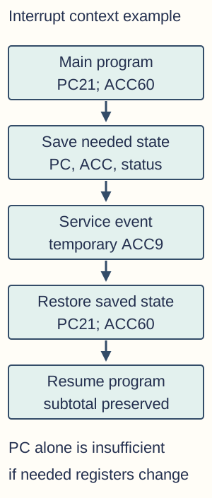
Saving volatile context — Before service, preserve the interrupted program's needed PC/return state, status and volatile registers under the convention. The interrupt service routine (ISR) or platform restores the saved state before resuming, so the main program does not inherit the service routine's temporary calculations. This does not normally mean copying every byte of all main memory each time; save the required execution context.
ISR behaviour and resumption — An ISR handles the relevant event, updates appropriate device/system state and acknowledges completion as required. It must preserve the promised context and return to the correct continuation. If ACC held a main-program subtotal and the ISR overwrote it without saving/restoring, the program could resume at the right address but compute the wrong answer.Illustrative interrupted context with PC 21 and ACC 60. Needed execution state is saved, the service uses temporary ACC 9, and restoring PC/status/register state permits correct continuation with subtotal 60. This does not require copying every RAM byte and is not a literal stack layout or real interrupt-vector address map.
Priorities, responsiveness and limits — Interrupts can improve response to asynchronous events, events occurring independently of the main instruction sequence, and avoid some wasteful polling, repeatedly checking whether attention is needed, but service work and context changes have overhead. Priorities and masking affect which request is handled first and whether another can interrupt service. More interrupts are not automatically faster; the event rate, handler cost and workload determine the effect.
Performance factors and memory hierarchy
Clock frequency and work — Higher clock frequency provides more cycles per second, potentially improving work rate when other factors are comparable. Instruction mix, cycles per instruction, cache misses, thermal constraints and I/O waiting can dominate. Comparing only GHz across different designs is not enough to determine application performance.
Multiple cores and parallel work — Multiple cores can execute suitable work in parallel, improving throughput or a parallelisable task. A serial dependency chain cannot simply be split into n equal independent pieces because n cores exist. Communication, contention and the serial fraction limit the speed-up, so doubling core count does not guarantee halving every task's runtime.
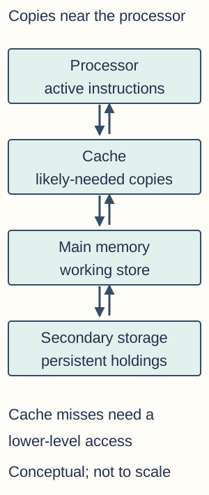
Cache role and locality — Cache holds copies of likely-needed instructions/data closer to the processor with lower access latency, a shorter wait for requested data, than main memory under the model. Temporal locality reuses recently accessed items; spatial locality accesses nearby locations. A cache miss requires a slower lower-level access, and caches need consistency rules when copies change; they are not simply extra persistent disk space.Conceptual processor/cache/main-memory/secondary-storage roles. Cache holds copies likely to be reused, not a substitute for all working memory or persistent storage. A cache miss needs an appropriate lower-level access. Arrows represent data movement between roles, not a claim that every CPU load automatically reads a disk.
Word length — Word length describes a processor's natural data width under a stated architecture convention, affecting register/ALU handling and representable values per native word. It is distinct from an instruction's possible variable length and from data/address bus widths. A wider word can reduce steps for some operations but does not make every program twice as fast or every string exactly one word long.
Address and data bus widths — More address bits allow more distinct locations under the addressing model, while more data bits can move a wider transfer per operation. Sixteen address bits versus seventeen doubles the possible location count, not automatically the clock rate. A wider transfer path helps only when memory/controllers/workload can use it; physical bandwidth, latency and addressing capacity are different concepts.
Evaluating a performance claim — Use a workload-relevant benchmark and state controlled differences, including instruction mix, memory/I/O access, compiler and parallelism. A larger cache can help a locality-friendly task but have less effect when the working pattern misses it. Link a hardware feature to a causal bottleneck rather than listing specifications as proof of an unconditional ranking.
Barcode, camera, laser printing and RFID
Barcode reader principle — A one-dimensional barcode encodes data in a defined pattern of dark/light widths. A laser/optical reader can measure reflected light as the pattern is scanned, convert it to a signal and decode under the symbology; camera-based imagers are another implementation. Check digits can detect some decode errors, but the label usually supplies an identifier rather than the full live price database.
Barcode suitability — Barcode labels can be cheap and quick to scan in retail or stock handling, but ordinary optical scanning needs the code visible and sufficiently clear. Dirt, damage, glare and poor orientation can cause failure. Two-dimensional codes and camera imagers have additional capabilities; do not assume every barcode reader uses one identical laser mechanism or stores unlimited product information.
Digital camera principle — A camera lens focuses light on an image sensor, such as a CMOS or CCD implementation, whose sites convert light into electrical measurements. Exposure, sampling/quantisation and processing create digital image data; colour filters and reconstruction can contribute colour estimates. The stored image can be compressed and include metadata; not every sensor site independently records a complete three-channel colour pixel in the same way.
Camera suitability and quality — Pixel count affects possible spatial sampling, but lens quality, sensor properties, lighting, noise, focus and compression affect the actual result. More megapixels alone do not guarantee sharper usable evidence or better low-light performance. Consider intended capture conditions, file size, required detail and transfer/storage needs for the task.
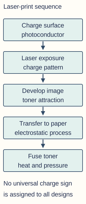
Laser printer principle — A laser printer forms an electrostatic image on a photosensitive drum/photoconductor, using controlled exposure to change charge patterns. Toner is attracted under the device's charge arrangement, transferred to paper and fixed by a heated/pressure fusing process. Explain the sequence without assuming all designs use the same sign of charge everywhere or that laser light directly burns each printed mark into paper.Electrophotographic printing sequence: establish a charged photoconductor surface, expose to form the image charge pattern, attract/develop toner, transfer and fuse. Exact polarity and component arrangements differ by implementation; the laser does not directly burn the final image into paper.
Laser printer suitability — Laser printing can suit frequent text/document output with useful throughput and durable fused toner, subject to the device's rated capabilities and running costs. Warm-up, colour requirements, consumables, paper handling and workload matter. A quoted pages-per-minute value for one mode does not guarantee every complex graphic or duplex job achieves that throughput.
RFID principle — Radio-frequency identification uses a reader and a tag with an antenna and stored identifier/data under a protocol. A passive tag can obtain operating energy through the reader's electromagnetic field; an active tag has a power source. The reader receives the tag response without requiring the same optical line of sight as a printed barcode under suitable conditions.
RFID suitability and limits — RFID can support asset/inventory tracking and contactless identification, but read range, frequency, tag type, materials and interference affect reliability. Multiple-tag reading needs protocol support rather than an assumption every tag responds successfully at once. An identifier read is not by itself proof of a person's identity or authorisation, and privacy/security choices affect a real deployment.
Persistent storage principles and choosing media
Why secondary storage — Secondary storage retains programs and data beyond working-memory use and commonly across power loss, with appropriate technology and retention conditions. Main RAM is typically volatile working memory, while disks/flash provide larger persistent storage under the system model. Persistence does not make a device immune to corruption, wear, accidental deletion or physical loss.
Magnetic hard disk — A hard disk stores data through magnetic patterns on rotating platters, read/written by heads positioned over the relevant tracks, with sectors identifying data regions under the format. Mechanical seek and rotational waiting contribute access latency, while sustained transfers depend on the data layout and interface. Random small accesses can perform differently from a long sequential transfer; capacity alone does not determine responsiveness.
Optical disk — An optical drive uses a laser and reflected-light differences under a disc format to read data. Pressed discs can use pits and lands; the detected sequence is decoded under the format rather than a universal pit=1 rule. Pressed, write-once and rewritable media use different physical recording mechanisms, such as structures, dyes or phase-change materials. State permitted rewriting and capacity rather than asserting every disc is rewritten magnetically or has identical pits produced by the user's drive.
NAND flash and SSD controller — An SSD combines nonvolatile flash cells with a controller managing addressing, error correction and write/erase behaviour. The course's simplified cell model stores charge affecting transistor behaviour; floating-gate and other charge-storage implementations exist. No moving seek head is required, but controller, interface, workload and flash condition still affect latency and throughput.
Pages, blocks and wear — Flash is programmed in pages under a defined technology, while erase operations generally act on a larger block containing many pages. Updating data can require writing a new location, marking old data invalid and later collecting/erasing a block rather than overwriting one arbitrary page indefinitely. Wear levelling spreads erase/write use; finite endurance and write amplification, additional physical writes beyond the amount of user data changed, mean no-moving-parts is not the same as unlimited lifetime.After a logical page update, a controller can place the new data in block B and mark the old page 1 in block A invalid. Other live pages 0 and 2 must be preserved elsewhere before erasing A. Pages are programming units and the larger block is the erase unit under the model; the diagram does not imply erasing live data safely without moving it.
Comparing media for a task — Compare capacity, access latency, sequential/random transfer behaviour, durability, portability, rewritability, cost and required interfaces for the actual workload. SSDs often reduce mechanical-latency limits; magnetic storage can suit large persistent collections and optical media particular distribution/archive needs under an appropriate plan. Avoid universal current price/speed rankings without a specified device and workload, and distinguish a storage choice from a complete backup strategy.
Test yourself
50 questions · Random sets of 10. These quick checks support revision; practise longer explanations and justified judgements too.
 Mr Kidman's Classroom